More pages: 1
2 3 4 5 6 ...
11 ...
12
Framework 4 (Last updated: October 25, 2019)Framework 3 (Last updated: February 6, 2017)Framework 2 (Last updated: October 8, 2006)Framework (Last updated: October 8, 2006)Libraries (Last updated: September 16, 2004)Really old framework (Last updated: September 16, 2004)
Metaballs 2
Sunday, August 25, 2019 | Permalink


 Executable
Source code
Metaballs2.zip (1.6 MB)
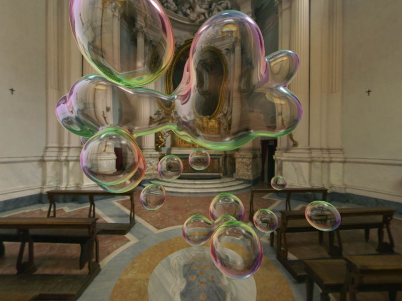
Required:VK_KHR_8bit_storageRecommended:VK_NV_mesh_shaderThis is a demo exploring the use of the Mesh Shader pipeline, which is a new compute-like pipeline for rasterization, allowing flexible processing and amplification of meshes. This demo is all amplification as there's no input mesh at all, and the only data is a small constant buffer with ball positions and radii. The output geometry is procedurally generated using Marching Cubes. A task shader is used for culling out cubes that aren't intersected by the isosurface, and a mesh shader generates the geometry for intersected cubes. Given that most cubes are empty space or fully inside the isosurface, this optimization results in more than an order of magnitude improvement in performance over just using a mesh shader.
While a number of optimizations have been employed and performance is a couple of orders of magnitude above the first naive implementation, it's probably possible to squeeze more performance out of it. In particular, I suspect processing several cubes per mesh shader invocation could improve performance. While all lanes get used for the field function evaluation, the number triangles per invocation is small and the output phase of the shader goes narrow. It may also be beneficial to go wider for the task shader, although the current lane utilization is near optimal.
This demo will run on any Vulkan capable GPU with the 8bit_storage extension using the compute shader fallback path. On GPUs supporting mesh shader (currently only NVIDIA RTX series (Turing)) you can toggle between mesh shader and compute implementation. Performance-wise both paths are roughly equal, with some differences depending on settings. The demo offers a number of options to toggle on the F1 dialog to compare implementations under different loads, including changing the number of balls, their size, and the grid density.
The compute implementation relies on a conservative memory allocation and could theoretically run out of memory and exhibit dropped geometry, although it has been set to a sufficiently high allocation that no artifacts have been observed. The allocation needed to support the absolute theoretical max is actually a full 27GB, which is larger than the GPU memory available on high-end GPUs as of this writing in 2019. In practice, the needed memory is far smaller than that.
BSP Blending
Monday, February 6, 2017 | Permalink
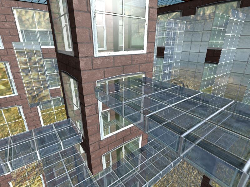
Back in the early days of consumer level 3D graphics hardware, BSP trees were a common component in rendering systems. Over time it fell out of fashion as the geometric complexity increased exponentially, scenes became more dynamic, and mesh data and processing moved over to the GPU side. With that said, BSP trees do have a number of desirable properties that made them attractive solutions for the static world geometry. One such property is that one can easily traverse a BSP tree in strict visibility order. If you don't have a depth buffer, you can render things correctly by traversing it back-to-front, and if you do have one, especially with Hi-Z rejection, you can instead traverse it front-to-back and get the maximum utilization of that hardware. Now this may not be a major concern today, but sorting things for transparency is still a problem we struggle to solve properly, and for static geometry a BSP tree can solve that quite elegantly.
So what this demo does is create a BSP tree to be processed on the GPU. While logically a binary tree, the layout in memory is linearly into an array, so as to be able to place it in a plain structured buffer for the GPU to read. The root node is the first element, then each element simply stores the size of the back-tree, which is enough information to be able to traverse the tree. A compute shader then does a parallel traversal of this BSP tree given the provided camera position, thereby producing an index buffer that is properly sorted back-to-front. The scene can then be rendered as a single draw-call. This index buffer is of course also reusable, so if no dividing plane in the tree has been crossed, there's no need to call the compute shader again. So a typical frame simply has a single plain draw-call with nothing really special about it. Then occasionally there's a frame with a BSP traverse call.
While the demo tracks when it needs to update the index buffer, it also provides a checkbox to disable this, so as to demonstrate its effect. If disabled, the rendering quickly becomes the usual unsorted mess of overlapping transparent geometry as you move away from the position of the last update.
Modern LightMapping
Tuesday, October 11, 2016 | Permalink
This demo is an alternative take on LightMapping, inspired a bit by Clustered Shading. I don't know if it's a particularly novel idea, or even particularly "modern", but decided to stick with this name over the alternative "Clustered LightMapping" that I also considered. In any case, after skimming the internet for state of the art implementations of lightmapping it would seem that neither Unreal Engine, Unity or any other popular engine out there, are doing anything similar, even though they have certainly advanced the baked lighting technology since the 90s.
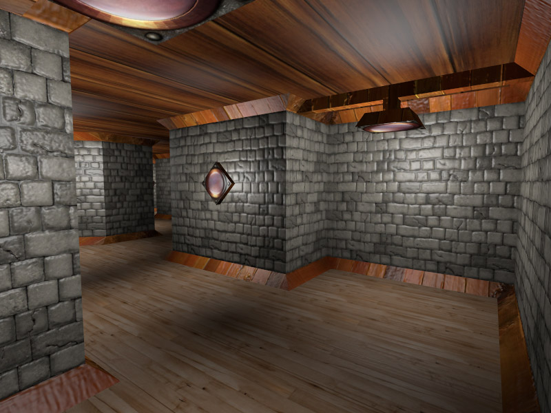
Why lightmapping in 2016? For the same reasons as in 1996 I guess. It can be really cheap and look really great compared to what you can accomplish in realtime with dynamic methods at a far greater cost. About once every year I launch the original Unreal, a game using old-school lightmapping, and find that the lighting has aged really well, whereas for instance its geometric detail is painfully bad in comparison. Often I find that we have sacrificed too much quality in the name of dynamic worlds and iterating time over the last decade or so.
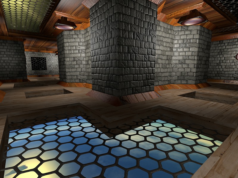
Old-school lightmapping simply stored a light value per texel, which was then multiplied with the diffuse texture and you were done. Unfortunately, that's not really compatible with normal mapping. Some engines solve that by using a lightmap in the distance and dynamic lighting closer up. This demo does lightmapping that's fully compatible with normal mapping, in fact, lighting is computed as with any dynamic light; however, a shadow term is stored for each light, and most importantly, a cluster map stores a bitmask of which lights affect a certain area. The cluster map is sampled with the same UV set as the lightmap; however, it can be of lower resolution. In this demo I made it half-res, but can also be smaller. The result is a lightmapping solution where the lights are stationary, but most attributes are dynamic and can vary, such as color, intensity, etc. If they have a radius, it can also shrink (but not grow), at the cost of some lost efficiency. This demo doesn't use range-based lights though. It would also be entirely possible to rotate the light if it's non-uniform or animate a projected texture. Again, not something I did in this demo. However, the dynamic property of intensity and color is demonstrated and you can interact with the lights in a number of ways.
With this technique it's also trivial to turn lights on and off with a simple bitmask and get all the performance back from the disabled lights. The use of the cluster map improves performance by about 60% compared to evaluating all lights, which presumably roughly matches how many lights affect the average surface in the scene. The scene, as usual, is my own really old and totally awesome coder art.
Clustered Shading
Tuesday, March 24, 2015 | Permalink
Clustered Shading is a technique for efficient lighting on modern GPUs, first proposed by
Olsson et. al., with which I have been evangelizing this technique for the last few years.
My contribution is an adaptation for practical use in a real AAA game engine. While I have provided slides and held several conference presentations on the subject, the game using this technique has as of this writing not yet been released, and I haven't published any running samples of it before. This demo attempts to fill that gap.
The main motivation for Clustered Shading is performance, flexibility, and simplicity. It normally out-performs competing techniques, such as tiled shading, and in particular the worst-case performance, which is what matters most. It's compatible with both deferred and forward shading, making it a unified lighting solution that doesn't interfere with any other technical choices.
This demo differs in a few ways from the implementation we are using in the Avalanche Engine, but the underlying principle remains the same. In this demo, forward shading is used, and because of that, MSAA just works. It's also using a very simple world-space clustering scheme, instead of the more typical view-space. Since the number of lights is fairly limited in this demo, I'm exploring encoding lights as bits in a bitfield. This may very well be good enough for AAA titles too, but won't scale forever. At some point a list of indices is going to be more compact and faster in practice. But for a lower workload, it makes one less indirection in the inner loop and keeps the memory fixed.
As a reference I have pretty much copied my Deferred Shading 2 demo from 2008, and made a few minor improvements to it. At the time I was fairly proud of it, but it doesn't really represent the state-of-the-art of Deferred Shading anymore. In particular it's a Classic Deferred implementation, which gets very bandwidth bound on modern hardware. With no MSAA I see Clustered Shading outperforming it by a factor of 2x, and with MSAA enabled the gap only widens, up to a 5x factor at 8xMSAA.
This demo should run on any DX11 capable GPU.
Phone-wire AA
Tuesday, June 26, 2012 | Permalink
Traditionally aliasing within a surface has been addressed with mipmapping and aliasing due to geometric edges has been handled by MSAA. While this setup usually works reasonably well it does not fully solve the aliasing problem. Lighting computations based on mipmapped samples can still introduce aliasing and there are certain geometry that can cause MSAA to break down.
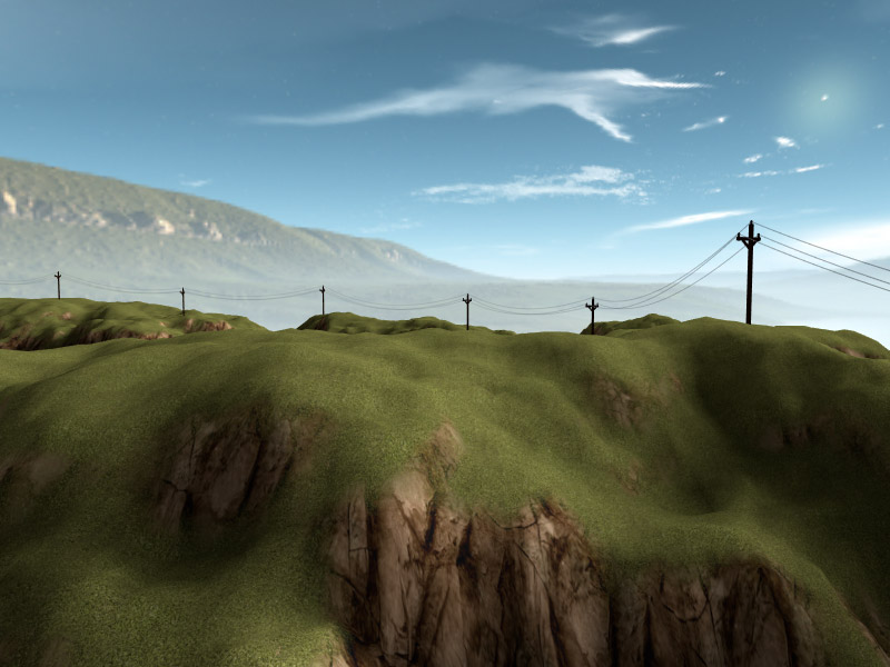
A common culprit of aliasing in games is phone wires. Due to the thin geometry they tend to get broken up into a bunch of random disconnected dots after a distance. MSAA helpes reduce the problem but doesn't fully solve it. It merely pushes the problem a factor further into the distance. Once past this larger distance, the same issues will start appearing even with MSAA. This demo illustrates a simple but effective technique for solving the problem.
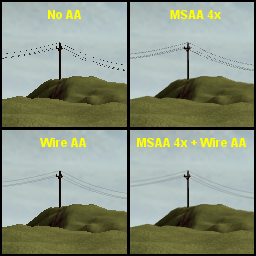
The idea is to adjust the radius of the wire to make sure it does not get smaller than a pixel wide. If the wire's radius would make it smaller than a pixel, it clamps the width to a pixel and instead fades with an alpha value corresponding to the radius reduction ratio. For example, if the wire is deemed to be half a pixel large at current distance, it clamps width to a full pixel and sets coverage to 0.5 instead. While the technique solves the problem of aliasing due to thin geometry, it does not address the general problem of jaggies; however, your regular MSAA will take care of that. With both enabled you get a very natural looking wire at any distance.
A similar approach could likely be used on other aliasing prone geometry based on thin geometry, such as antenna towers, pipes and railings.
This demo should run on any DX10 capable GPU.
Second-Depth Anti-Aliasing
Sunday, August 28, 2011 | Permalink

Executable
Source code
SDAA.zip (1.3 MB)
Required:Direct3D 10Recommended:Direct3D 10.1This demo shows another anti-aliasing technique using the depth buffer and a second-depth buffer for locating the edges. First edges are deteced. Then for each edge pixel it is determined whether an edge is cutting through this pixel or not. There are essentially two types of edges in a scene: creases and silhouette edges. When there's a crease the distance to the edge can be found by sampling two neighbors to the left and two the right and computing the intersection point where they meet, and similarly vertically of course. For silhouette edges there's a gap in the depth values so this doesn't work. So we use a buffer of second-depth values for this case, i.e. the depths of the backfaces in the scene, and use the same logic with those values and compute the intersection point in the same fashion. Once the edges are found we blend with a neighbor pixel in the same fashion as in GPAA/GBAA.
This technique is less intrusive to the overall rendering and should be easier to integrate into an existing engine than GPAA/GBAA. The only addition is the second-depth buffer. If the engine already has a pre-Z pass this can be altered into a second-depth pass by switching to front-face culling. Depending on the scene this may turn out faster or slower than a regular pre-Z pass. In this demo second-depth is in fact faster.
On the downside, this technique requires that there indeed are backfaces behind edges. This means that thin objects, billboards/foliage etc., will not get antialiased unless extra backside geometry is added. Quality-wise it rivals that of GPAA/GBAA, but requires good precision in the depth buffer to work.
This demo should run on any DX10 capable GPU.
Geometry Buffer Anti-Aliasing (GBAA)
Monday, July 18, 2011 | Permalink
Executable
Source code
GBAA.zip (2.3 MB)
Required:Direct3D 10GBAA is another anti-aliasing technique that works in the same spirit as GPAA, with the same quality, but with a substantially different method to accomplish the results. Whereas GPAA operates entirely as a post-process step (plus optionally pre-processing edges), GBAA uses a mixed method. During main scene rendering the geometry information is stored to a separate buffer, alternatively it uses available channels in an existing buffer. Anti-Aliasing is then performed in the end, in a resolve-pass if you will, as a fullscreen pass using the stored geometric information.
The geometry is represented as a two-channel edge distance. The closest direction (horizontal/vertical) distance is stored and the other is set to zero. It is possible to pack it into one channel and only store a bit indicating the major direction, but this demo uses two channels for simplicity.
A geometry shader is used during main rendering to compute the edge distances within a triangle. These are passed down in three components of an interpolator. The pixel shader simply selects the shortest distance to output to the buffer.
The advantage of GBAA over GPAA is that it gets rid of the second geometry pass. It also does not require any line drawing, something that consumer level GPUs generally suck at. Additionally, having geometry information in a buffer allows us to anti-alias other edges than just geometric ones, most notably alpha-tested edges. The shader just needs to output the distance to the alpha-edge, something that's easily approximated using gradient instructions. This is also demonstrated in the demo. On the down side it requires additional memory for the geometry buffer, but does not balloon up in the same way as MSAA does.
This demo should run on any DX10 capable GPU.
Geometric Post-process Anti-Aliasing (GPAA)
Saturday, March 12, 2011 | Permalink
Executable
Source code
GPAA.zip (1.2 MB)
Required:DirectX 10Recently a number of techniques have been introduced for doing antialiasing as a post-processing step, such as MLAA and just recently SRAA. MLAA attempts to figure out the underlying geometric properties by analyzing the pixel colors in the final image. This can be complemented with depth buffer information such as in Jimenez's MLAA. SRAA uses super-resolution buffers to figure out the geometry. This demo shows a different approach which instead of trying to figure out the geometry instead passes down the actual geometry information and uses that to very accurately smooth geometric edges.
The technique is relatively simple. The scene is initially rendered normally without any antialiasing. Then the backbuffer is copied to a texture and the geometric edges in the scene are drawn in a post-step. The edges are drawn as lines and for each shaded pixel the shader checks what side of the line the pixel center is and blends the pixel with a neighbor up or down in case of a mostly horizontal line, or left/right in case of a mostly vertical line. The shader computes the coverage a neighboring primtitive would have had on the pixel and uses that as the blend weights. This illustration shows the logic of the algorithm:
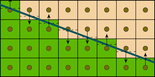
The wide line is the geometric edge. The arrows show how the neighbor pixel is chosen. The dashed lines shows the value of line equation for that pixel, which is used to compute the coverage value. The coverage and neighbor pixel is all that's needed to evaluate the anti-aliased color. The blending is done by simply shifting the texture coordinate so that the linear filter does all the work, resulting in a single texture lookup needed.
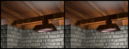
Unlike many other antialiasing techniques, this technique really shines for near horizontal or near vertical lines. The worst case is diagonal lines, but the quality is good in all angles. Here is a sample image with and without GPAA.
The main advantage of this technique is performance and quality. The actual smoothing of edges is quite cheap. Instead the biggest cost is the copying of the backbuffer. On a HD 5870 this demo was rendering a frame at about 0.93ms (1078fps) at 1280x720, of which the backbuffer copying costed 0.08ms and edge smoothing 0.01ms. For games using posteffects the backbuffer will likely have to be copied anyway. In such a case an alternative approach is to render the smoothing offsets directly to a separate buffer and then sample the backbuffer with those offsets in the final pass. This way you could avoid doing an extra backbuffer copy.
The main disadvantage of this technique is that you need to have geometric information available. For game models it is fairly straightforward to extract the relevant edges in a pre-processing step. These need to be stored however which takes additional memory, alternatively a geometry shader can be used. The extra geometric rendering may be a fair bit more costly in real game scenes than in this demo.
An artifact can sometimes occur when there are parallel lines less than a pixel away from each other. This could result in partly smooth and partly jagged edges which sometimes look worse than the original aliased edge.
A small issue is that due to precision and different computations the shader code may for some pixels decide the edge went on the other side of the pixel center than what the rasterizer thought, in case the edge passes almost exactly across the pixel center. This results in single pixel artifacts in otherwise smooth edges. This is generally only noticable if you look carefully over static pictures.
Future work:
It would be ideal to come up with an offset buffer together with the main rendering to avoid the extra geometric pass. Ideally a hardware implementation could generate the values during rasterization of the scene into a separate buffer. Edge pixels would get assigned a blending neighbor and a coverage value. With say 8 bits per pixel, of which 2 bits are for picking neighbor and 6 bits for coverage, it would likely look good enough. Theorethically it would represent coverage as good as 64x MSAA. Alternatively a more sophisticated algorithm could use 3 bits for all eight neighbors and 5 bits for coverage. A hardware implementation could avoid the single-pixel error mentioned above.
For software approaches one might consider using a geometry shader to pass down the lines to the pixel shader. The geometry shader could use adjacency information to only pass down the relevant silhouette edges and avoid internal edges. It might be possible to render out the offsets directly in the main pass with this information, although the buffer might have to be post-processed to recover missed pixels outside of the primitive.
In any case, there's a lot of potential and I'll surely be playing more with this.

More pages: 1
2 3 4 5 6 ...
11 ...
12